In the process of CO2 gas shielded welding, welding spatter is the biggest disadvantage, which is related to the transition pattern of the welding wire droplet. Therefore, the best way to solve the droplet transfer can improve the welding spatter. Therefore, we should start with improving the performance of the welding equipment and using different welding processes.
1. Improvement of welding equipment
Based on the control principle of combining waveform control and short-circuit current grooming, a new welding equipment IGBT inverter low-spatter CO2 gas shielded welding machine was developed. When using this welding machine, there is less spatter, beautiful welding seam formation, excellent welding quality, main circuit, The control circuit is simple and reliable.
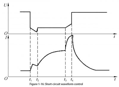
1) Short-circuit current waveform control In the process of CO2 gas shielded welding, according to the characteristics of the two phases of arcing and welding wire short-circuit, the principle of variable structure circuit design is used to design the control circuit into an arcing circuit and a short-circuit current control circuit. According to the state of the molten wire droplets during the welding process, the instructions issued by the control circuit are judged to switch in a timely manner: In the short-circuit stage, the CO2 gas shielded welding system is designed as a current follower to make the output welding current change with the given value. Change, and in the initial stage of the short circuit, the short circuit current is used to divert the welding arc part to reduce the welding spatter in the initial stage of the short circuit.
The short-circuit current waveform control can be divided into three methods: instantaneous short-circuit control, normal short-circuit control, and short-circuit time control.
(1) Instantaneous short-circuit control (t1 to t2). When the short-circuit current waveform control detects a short-circuit between the welding wire droplet and the weld pool, the transient short-circuit control is first performed to reduce the short-circuit current and control the speed of the instantaneous short-circuit current rise, so that the welding wire droplet drops with the welding current at a lower current value. The full contact of the seam weld pool achieves a slow transition and can reduce welding spatter caused by transient short circuits. The waveform control (t1 ~ t2) in the transient short-circuit control phase is shown in Figure 1-16.

(2) Normal short circuit control (t2 ~ t3). After controlling the instantaneous short circuit, keep the low current value in the welding circuit for a certain period of time, and then control the current flowing through the short circuit liquid bridge to increase with a smaller slope. While ensuring sufficient electromagnetic compression, reduce the short circuit current. The peak value to reduce the welding spatter caused by the short-circuit fluid bridge necking and bursting during the short-circuit stage. The waveform control (t2 ~ t3) in the normal short-circuit control phase is shown in Figure 1-16.
(3) Short circuit time control (t3 ~ t4). When the short-circuit time is too long and exceeds the normal short-circuit time, the control of the rising speed of the short-circuit current is immediately released, so that the current is increased at a normal speed, which accelerates the breakage of the welding wire’s neck and causes the droplet to quickly melt into the weld. Pool transition to avoid affecting the stability of the welding process because the short circuit time is too long and the welding wire droplet growth is too large. The waveform control (t3 ~ t4) in the short-circuit time control period is shown in Figure 1-16.
2) Short-circuit current grooming circuit
In order to quickly and effectively control the instantaneous current value at the initial stage of the short circuit, a signal of short circuit between the welding wire droplet and the weld pool was obtained from the Hall voltage sensor in the short circuit current grooming circuit, and was converted into a pulse by the input of a monostable trigger. Signal output. The pulse signal is sent to the integrated driver through the inverter to drive the IGBT module, so that the short-circuit current dredging circuit is instantly turned on. Because the IGBT module and the welding arc are connected in parallel, the welding arc current is partially shunted. It can be seen that the arc current in the welding circuit can be effectively and timely controlled within 300 μs after the short-circuit of the welding wire droplet and the weld pool.
2. Choice of welding process
1) When using CO2 plus O2 mixed with CO2 gas shielded welding, the welding process is not stable enough. If CO2 gas is added in a volume fraction of 15% to 20% O2, the oxidizing property of the protective gas will be strengthened, and the metallurgical reaction of the welding process will generate greater heat, thereby reducing the surface tension of the liquid metal and improving the droplet transfer of the welding wire. And the fluidity of the weld pool metal. At the same time, due to the addition of O2, the metallurgical reaction in the welding process is more intense, the hydrogen content in the weld is lower, and the crack resistance of the welded joint is improved.
2) CO2 plus Ar mixed use Adding Ar to CO2 gas reduces the thermal conductivity of pure CO2 gas in the temperature range of the welding arc and consumes a large amount of heat from the welding arc, so that the arc column and arc spot are strongly contracted. There will be welding spatter. In short-circuit transition welding, φ (CO2) 50% + φ (Ar) 50% is generally used; in non-short-circuit transition CO2 gas shielded welding, φ (CO2) 30% + φ (Ar) 70% is generally used. When using CO2 plus Ar mixed gas for welding, in addition to reducing welding spatter, it can also improve weld formation, reduce weld height and penetration, and increase weld width.
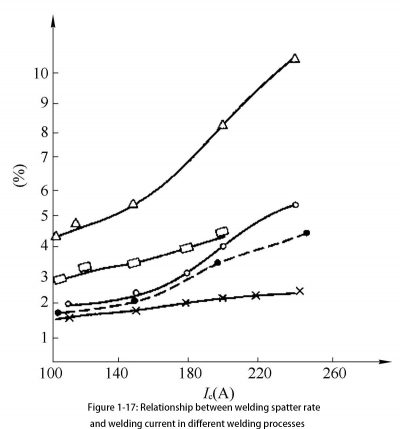
3) Using a pulsating wire feeding system In CO2 gas shielded welding, a pulsating wire feeding system is used instead of the conventional constant velocity wire feeding, so that when the welding wire is pulsating, a short circuit occurs with the weld pool, making the short circuit transition The frequency is basically the same as the frequency of the pulsating wire feeding. The short-circuit current peaks are not only uniform, but also the values are not high, thereby reducing welding spatter. If on the basis of pulsating wire feeding, combined with current waveform control (which controls welding spatter), the effect of ensuring a stable transition of the welding wire droplet will be better. The relationship between welding spatter rate and welding current in different welding processes is shown in Figure 1-17.

4) Using pure CO2 gas-filled cored wire process. When pure CO2 gas shielded welding, the welding spatter is large, and the weld formation is worse than that of electrode arc welding. When using the pure CO2 gas flux cored wire welding process, the welding process is combined with gas and slag, which overcomes the shortcomings of pure CO2 gas shielded welding. Its main process features are as follows:
(1) Welding spatter is small. By changing the composition of the flux-cored welding wire, the surface tension of the welding wire droplet and the molten pool is changed, thereby reducing the volume of the droplet, realizing the spray transition, and reducing welding spatter.
(2) There are few air holes in the weld. By increasing the FeC2 of the flux-cored wire, reducing TiO2, etc., the porosity of the flux-cored wire bead is less than that of the solid-core CO2 wire.
(3) High weld toughness. Deoxidizer with flux-cored wire reduces the oxygen content in the weld and improves the low-temperature toughness of the weld.
(4) High welding speed. Because the metal sheath of the flux-cored wire is very thin, the welding current density is large, and the heat of the length of the extended portion of the wire is relatively large, thereby forming a welding feature with a high melting rate of the flux-cored wire. Compared with electrode arc welding, continuous welding of flux-cored wire replaces the interrupted welding of electrode arc welding due to electrode replacement, which significantly improves the welding deposition speed.
(5) Welding depth is large. Due to the large current density of the flux-cored wire, not only the penetration depth of the butt bead is deeper, but also the penetration depth of the root of the fillet welding is increased. Compared with solid cored wire CO2 gas shielded welding, the workload of rework repair due to poor fusion is reduced. .
(6) Vertical welding suitable for large welding speed. When CO2 gas shielded doped cored wire is used for vertical welding, the molten metal is firmly supported by the slag with high viscosity and high solidification point to form a perfect weld. During the vertical welding process with a large welding speed, the welding current is about twice that of the solid core wire.
(7) Flux-cored wire CO2 gas shielded welding can weld stainless steel. Due to the role of acid oxides such as TiO2 and silica sand in the flux-cored wire, Cr and C in stainless steel no longer undergo metallurgical reactions. CO2 gas protection is used during welding as much as possible, but the carbon content in the deposited metal is not. It is increased to avoid intergranular corrosion during the CO2 gas shielded welding of stainless steel solid cored wire.
(8) Welder operation technology is easy to master. Compared with solid cored wire CO2 gas shielded welding, in the flux-cored wire CO2 gas shielded welding process, due to the joint protection of slag and CO2 gas, not only the welding spatter is less, the weld seam is formed better, and the welder operation technology is easy to master. The required training time is correspondingly reduced.