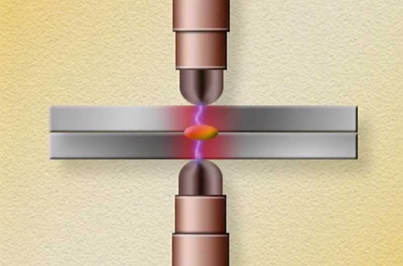
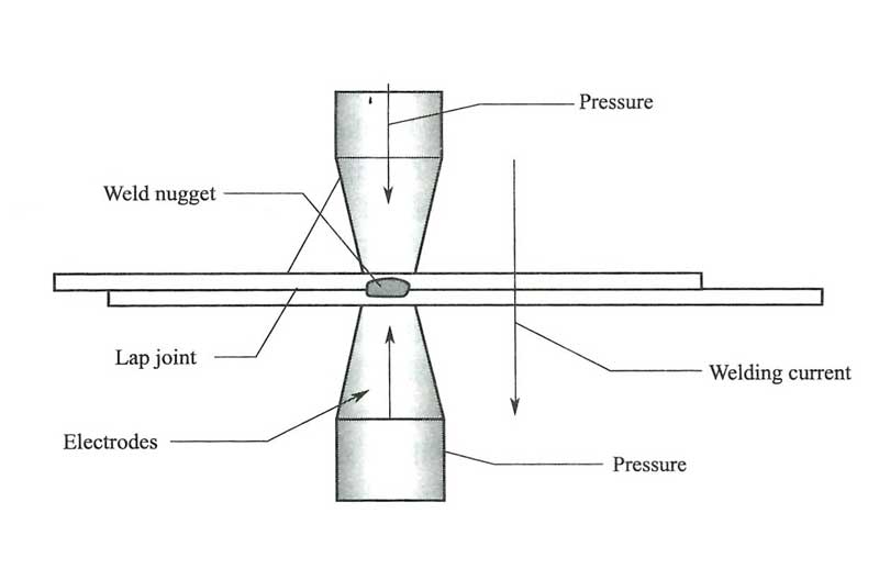
The simplest form of the resistance welding process is resistance spot welding (RSW) where the pressure is provided by clamping two or more overlapping sheets between two electrodes (Figure 2). A current is then passed between the electrodes, sufficient heat being generated at the interface by resistance to the flow of the current that melting occurs, a weld nugget is formed and an autogenous fusion weld is made between the plates.

Figure 1 Resistance Spot Welding
Heat sources and process
For resistance spot welding (RSW), the heat generated depends upon the current, the time the current is passed and the resistance at the interface. The resistance is a function of the resistivity and surface condition of the parent material, the size, shape and material of the electrodes and the pressure applied by the electrodes.

Figure 2 Process of resistance spot welding
A modification of Ohm’s Law may be made when watts and heat are considered synonymous. When current is passed through a conductor the electrical resistance of the conductor to current flow will cause heat to be generated.
- There are six major points of resistance in the work area. They are:
- The contact point between the electrode and top workpiece.
- The top workpiece.
- The interface of the top and bottom workpieces.
- The bottom workpiece.
- The contact point between the bottom workpiece and the electrode.
- Resistance of electrode tips.
Current value is in the same in all parts of the electrical circuit, the resistance values may vary considerably at different points in the circuit.
The general heat generation formula for resistance welding is:
H= I2Rt
where “I” is the weld current through the workpieces, “R” is the electrical resistance (in ohms) of the workpieces, “t” is the weld time (in hertz, milliseconds or microseconds). The weld current (I) and duration of current (t) are controlled by the resistance welding power supply. The resistance of the workpieces (R) is a function of the weld force and the materials used.
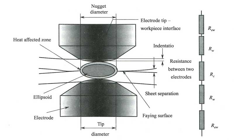
The diagram (Figure 3) illustrates three contact and four bulk resistance values, which, combined, help determine the heat generated. Total resistance is the sum of the following:
CONTACT RESISTANCE (Rc + 2Rew) is a function of the extent to which two surfaces mate intimately or come in contact. Contact resistance is an important factor in the first few milliseconds of a weld. The surfaces of metal are quite rough if they are examined on a molecular scale. When the metals are forced together with a relatively small amount of force, some of the peaks make contact. On those peaks where the contact pressure is sufficiently high, the oxide layer breaks, forming a limited number of metal-to-metal bridges. The weld current is distributed over a large area s it passes through the bulk metal. However, as it approaches the interface, the current is forced to flow through these metallic bridges. This “necking down” increases the current density, generating enough heat to cause melting. As the first of these bridges melt and collapse, new peaks come into contact, forming new bridges and additional current paths. The resistance of the molten metal is higher than that of the new bridges so that the current flow transfers from bridge to bridge. This process continues until the entire interface is molten. When the current stops, the electrodes rapidly cool the molten metal, which solidifies forming a weld.

Figure 3 Resistance of resistance spot welding (RSW)
Factors Affecting Heat Generation (Q):
(1) Surface condition causes inconsistent welds by inhibiting intimate contact at the weld joint. Preventive actions include pre-cleaning the workpieces.
(2) Electrode force. The proper and consistent application of force improves the mating of the materials increasing the current paths, reducing the interface resistance, and insuring that any oxide barriers between the workpieces are broken through.
BULK RESISTANCE (2Rw) is a function of temperature. All metals exhibit a Positive Temperature Coefficient (PTC), which means that the bulk resistance increases with temperature. Bulk resistance becomes a factor in longer welds.
Principles and parameters
Resistance spot welding (RSW) is by far the most widely used variant of the resistance welding process. The basic principles of the technique are illustrated in Figure 2. The weld nugget extends through the sheets but without melting the surfaces of the outer plates. The main welding parameters are current, pressure and time. The amplitude and duration of all force and heating parameters can be defined in the “weld schedule.” It is recommended that when developing a welding procedure the electrode sizes, the welding time and the welding force should be selected first and the welding current increased until the desired nugget size is achieved.
The welding force required by three phase frequency converter equipment is 2 to 5 times that of the single phase AC units and for three phase secondary rectified machines somewhere in the region of 0. 5 to 2 times. Excessive forging force will result in indentation of the sheets, increased distortion and sheet separation. Too low a forging force results in metal expulsion, surface burning because of poor contact, tip pickup or contamination and internal defects of porosity and cracking.
If a forging force is required to assist in consolidating the weld, particularly for the crack- sensitive alloys this should be in the region of 2. 5 to 3 times the welding force. Welding current for three phase frequency converter units should be some 30% higher than for the single phase AC units.
A controlled up slope on the welding current, over two or three cycles, enables the electrodes to seat on the surface reducing metal expulsion and surface overheating. A downs-lope or current decay reduces the rate of solidification and assists in consolidation of the weld nugget if a post weld forge is used.
Electrodes
The bulk of the cost of a spot weld is the cost of dressing or replacing the electrode, the life being defined as the number of spot welds that can be made with a pair of electrodes while maintaining a minimum weld nugget diameter. Pick-up of alloys on to the tip and rapid wear are the two main reasons for the short life of spot welding electrodes. High welding currents, surface finish and electrode forces further assist in shortening the electrode life. It is not uncommon in very high- quality applications such as aerospace for the electrode to require cleaning after as few as 20 spot welds.

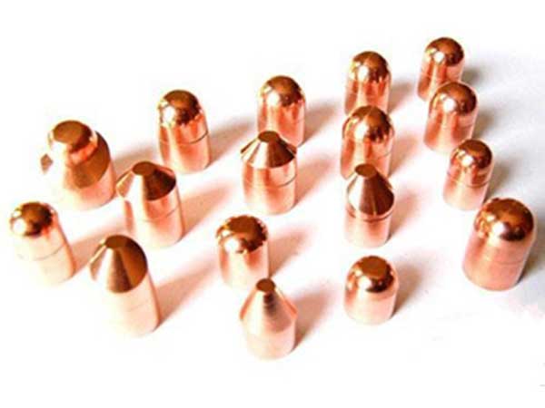
Figure 4 Spot Welding Electrode Tips
Electrode life may be extended by the use of replaceable caps on the electrode tips or, it is claimed, by the use of copper alloys with increased hardness which reduces mushrooming of the tip. Increases in hardness can be achieved by alloying with zirconium or cadmium-chromium and dispersion hardened with aluminium oxide. Of these the 1% Cd Cu are used for the softer alloys with the harder 1% Cr Cu or 21% Cr Zr Cu alloys for the welding of the cold-worked or age-hardened alloys.
The profile of the electrode tip is important with respect to both the tip life and weld quality. Tips may be conical, truncated conical, flat, domed or cylindrical. Of these types the truncated cone and the dome predominate. The most commonly recommended shape is the domed tip, the shape of which is more easily maintained in production than the truncated cone. Alignment is also less of an issue and is favoured particularly for portable equipment. The truncated cone tends to be used for commercial quality applications, mainly because electrode alignment is more critical and difficult to maintain consistently in production. Tip life, however, is markedly better, by a factor of two to three, than can be achieved with the domed electrode. Cone angles vary from 60° to 150° including an angle with a slight radius on the tip which aids in alignment and reduces marking of the sheet. The tip profile may be maintained by grinding, filing or by the use of abrasive cloth in a shaped former. While this dressing operation may be performed manually it is difficult to maintain the correct tip shape and electrode alignment. The use of automatic tip dressing tools or specially designed hand held manual or pneumatic tip dressers is strongly recommended.
Efficient electrode cooling is also necessary to maintain tip life. Large diameter electrodes will provide a greater heat sink but efficient water cooling is imperative. The cooling channel should be carried as close to the tip as possible, a distance of between 12 and 20 mm being usual with water flow rates of 5-10 litres/min. Water inlet temperature should be in the region of 20°C and the outlet temperature in the region of 30°C.
Get Notified of New Articles
Leave your email to get our weekly newsletter.


