Shielded metal arc welding (SMAW) is the most widely used welding method in industrial production. Shielded metal arc welding is to use the heat generated by arc discharge (commonly known as arc combustion) to melt the electrode and the workpiece and form a weld after condensation to obtain a welding process of a strong joint.
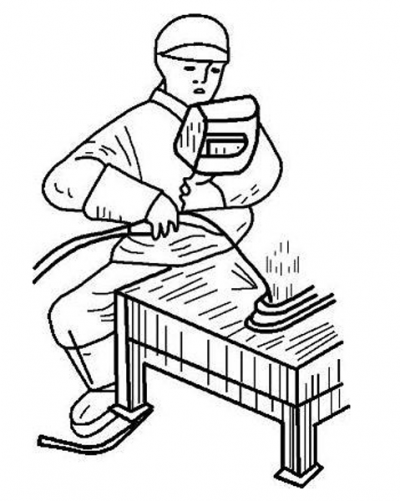
Characteristics of SMAW
Shielded metal arc welding (SMAW) is an arc welding process wherein coalescence is produced by heating with an electric arc between a covered or “coated” metal rod called the electrode and the work. Shielding is obtained from decomposition of the electrode covering, and filler metal is obtained from the electrode’s metal core and metallic particles in the covering. The source of the shielding and filler metal varies with electrode design. The shielding and filler metal largely control the mechanical, chemical, metallurgical and electrical characteristics.
Like the other electric arc welding processes, shielded metal arc welding employs the heat of the electric arc to bring the work to be welded and a consumable electrode to a molten state. The work is made part of an electric circuit known as the welding circuit (Figure 1). This circuit includes a source of power,welding cables, an electrode holder,a ground clamp and the consumable welding electrode. One cable carrying current from the power source is attached to the work, and another cable is attached to the electrode holder.
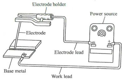
Figure 1 Circuit diagram for SMAW
Welding begins when an electric arc is formed or struck between the metallic electrode and the work. The intense heat of the arc melts the electrode and the surface of the work adjacent to the arc. Tiny globules of molten metal rapidly form on the tip of the electrode and transfer through the arc into the molten pool or weld puddle on the work’s surface. If the welds are flat or horizontal, the actual transfer is induced by the force of gravity, molecular attraction and surface tension. Molecular attraction and surface tension are the forces that induce metal transfer from the electrode to the work where the weld is being made in the vertical or overhead position. The arc is moved along the work, melting and fusing the metal as it progresses. Since the arc is one of the hottest commercial sources of heat (temperatures, above 9000 ℉ /5000℃ have been measured at its center), this melting takes place almost instantaneously as the arc is applied to the metal.
Welding can be accomplished with either alternating current (AC) or direct-current electrode negative (DCEN), straight polarity, or direct-current electrode positive (DCEP), reversed polarity.
When the electrode cable is fastened to the negative pole of the generator and the work to the positive pole, the polarity is positive, or more commonly referred to as straight polarity, shown in Figure 2-2. If the electrode cable is attached to the positive terminal of the generator and the ground clamp cable (the cable leading to the work) to the negative terminal, the circuit is called reversed polarity, shown in Figure 2. This will happen, of course, only on a DC welding machine.
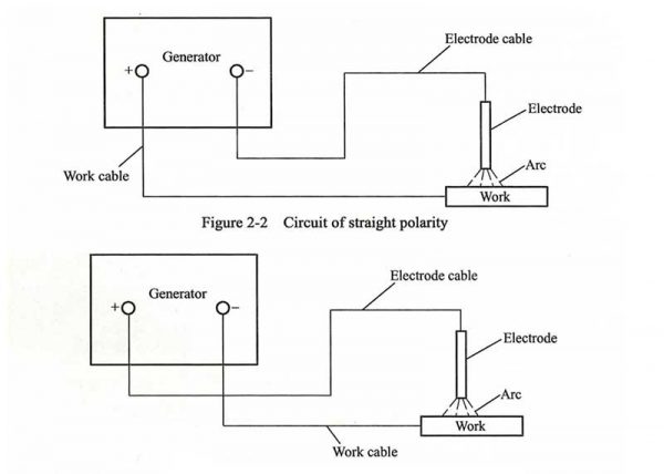
Figure 2 circuit of reversed polarity
Shielded metal arc welding process is one of the most popular arc welding processes. It has maximum flexibility and can weld many metals in all positions from near minimum to maximum thickness. The investment for equipment is relatively small.
This process can be used to weld steels and some of the nonferrous metals. It is used for joining steels, including low- carbon or mild steels, low-alloy steels, high-strength steels, quenched and tempered steels, high-alloy steels, stainless steels, and corrosion-resistant steels, and for welding cast irons and malleable irons. It is used for welding nickel and nickel alloys and welding copper and some copper alloys. It can be, but rarely, used for welding aluminum. It is not used for welding magnesium, the precious metals, or the refractory metals. Shielded metal arc welding is also used welding nickel and nickel alloys and welding copper and some copper alloys. It can be, but rarely, used for welding aluminum. It is not used for welding magnesium, the precious metals, or the refractory metals. Shielded metal arc welding is also used for surfacing.
Welding Techniques for SMAW
Shielded metal arc welding electrodes are made with core-wire diameter from 2.0 to 10mm. For all but exceptional circumstances, however, the useful range is 2.5~6.3mm. The length of each electrode depends on the diameter, for small-diameter electrodes where manipulation of the electrode calls for the greatest control the electrode may be only 300mm long. Generally, however, electrodes are manufactured to a length of 450mm and are consumed at a burn-off rate of 200~250mm/min. At one end of the electrode the coating is removed during manufacture so that it may be gripped in the electrode holder through which the welding current is introduced.
For economic reasons the welder should use the largest diameter of electrode suitable for each application. Because positional welding requires precise control of a small weld pool, smaller sizes of electrode are used for this purpose than for downhand welding where the pool is shaped by gravity. In multi-pass welding in fillets or grooved joints the first pass is usually laid using a smaller-diameter electrode to obtain better access and root penetration.
The welder’s task is to direct the arc into the joint so that metal is deposited where required and to manipulate the electrode by whipping or weaving so that the arc force holds the metal in position and sweeps aside the slag. An electrode is never held perpendicular to the joint but is usually inclined so that an angle of about 110° is subtended between the weld bead and the electrode. As shown in Figure 3. This is sufficient to allow the welder to see the crater beneath the arc and for the arc force to prevent the undesirable flow of slag ahead of the advancing crater.
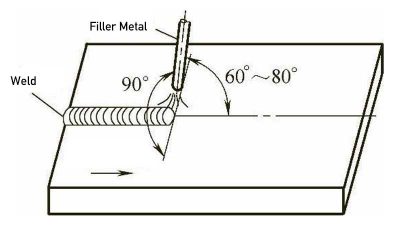
Figure 3 The angle subtended between the weld bead and the electrode
When welding some wide welds, the arc must be weaved so that the arc can reach the edges of the groove. When weaving, the weaving width, the pause at the end of weaving and other movements are important. The welder must pause at each end of weaving to allow for complete fusion into the side. The welder should quickly move across the center of the weld since the heating is more concentrated in the center than at the edges. The weaving width for low-hydrogen electrodes should not exceed 5/2 times the core wire diameter. For other electrode types this can be doubled. In general, the paths of weaving arc have several types as shown in Figure 4.
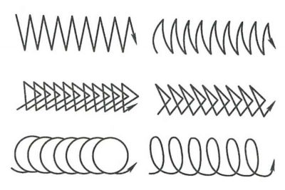
Figure 4 Several usual paths of weaving arc for SMAW
As the process is intermittent a welder will usually have to stop and fit a new electrode many times in the course of making each weld. If the arc is broken by the electrode being withdrawn, at the end of each electrode the weld crater will solidify without being fed by liquid metal and may form a crater pipe. To avoid this, the arc is broken by drawing the electrode slowly back along the bead while at the same time lengthening the arc. Before the next electrode is used, the slag which has solidified over the crater must be chipped away to avoid slag inclusions. The arc from the new electrode is struck ahead of the crater and moved back to take up the end of the previous bead. The stop/start position at electrode changes is a serious source of slag inclusions, porosity and lack of fusion. This part of the welding technique must be mastered thoroughly if the welder is to produce quality work.
Current, voltage (arc length) and speed are important process variables. Low current will give an irregular weld bead which sits on top of the plate; a high current will give good fusion but with excessive spatter. Short, low-voltage arcs give irregular beads with poor penetration and a tendency to slag inclusions; high voltages and long arcs result in spatter and a tendency to pick up nitrogen from the air, giving porosity. High welding speeds result in peaky, undercut beads; low welding speeds cause broad beads which tend to overlap on the work.
Get Notified of New Articles
Leave your email to get our weekly newsletter.


